l00nix's RPi blog My RPi musings and projects
My Custom (Automated) LiM Kubernetes Cluster
My journey on how I built a custom Raspberry Pi Compute Module 4 based k3s cluster and how I turned it from an idea into reality!
Table of Contents
- Intro
- 1 - Developing the LiM Cluster CM4 Carrier Board
- 2 - Designing The (LiM) Raspberry Pi cluster (Pringles) tray
- 3 & 4 - Putting it all together - Building the cluster
Intro
Inspired by “Network Chuck”’s video tutorial “i built a Raspberry Pi SUPER COMPUTER!! // ft. Kubernetes (k3s cluster w/ Rancher)” on YouTube and the corresponding course on his website, as well as Jeff Geerling’s video channel and blog, I set out on four different learning experience paths:
- The first led me down my father’s footsteps of electrical engineering, designing and building a custom carrier board for the Raspberry Pi compute module.
- The second, was designing a cluster tray that would house my cluster in a unique way, inspired by toilet paper rolls and a Pringles tube. But more about that later.
- The third, learning and creating kubernetes clusters on Raspberry Pis with kubernetes/k3s - a light weight version of kubernetes and managing them with Rancher.
- The fourth, learning a new to me way of automating/simplifying administrative tasks, cluster installs, and management using Ansible.
I should add that I am well down the path of my career, but I have always enjoyed tech and Linux. However, I am doing all of this as a hobby. I am sure there are many different (and possibly better) ways of doing things, but this was my way.
1 - Developing the LiM Cluster CM4 Carrier Board
Watching Jeff Geerling’s video New Raspberry Pi Projects - CM4 NAS, Piunora, and Seaberry! where he talks about mebs_t’s self designed NAS, made me think I am interested in doing something like this too. At the time, the use case I was working on was staking Navcoin headlessly with a Raspberry Pi Compute Module 4.
I was looking for a Raspberry Pi Compute Module 4 (CM4) carrier board that only provides power to a CM4 with WiFi and emmc storage. Many of the carrier boards out at the time provided a lot more functionality, so set out to design and build the Less-is-More (LiM) carrier board.
What I was looking for was a minimalistic board and I had a conversation with Jeff Geerling when I asked him if he knew of a more minimalistic design than this board? He pointed me to uptime.lab’s Upberry.
Neither of these boards are exactly what I was looking for for my use case. So I was motivated to design my own, customized board to my specs and that’s how the Less-is-More board series came to be.
The RPi CM4 - LiM Carrier Board series
The original idea of the LiM Carrier Board series was to build a series of minimalistic Raspberry Pi (RPi) Compute Module 4 (CM4) Carrier Boards. Less-is-More (LiM) refers to the minimalistic design only providing the most rudimentary functionality to the CM4 such as 5V power via USB-C power connector and two status (power/activity) LEDs for the original LiM Carrier Board version. An additional LiM+ version of the LiM Carrier Board featured additional functionality by adding flashing capability through a jumper.
Except for the LiM CM4 Cluster Carrier Board, the LiM and LiM+ Carrier boards are meant for CM4 boards with onboard storage (the LiM CM4 Cluster Carrier Board supports both CM4 versions with and w/o eMMC (lite version), micro SD card, and 2232 and has a 2241 M.2 M-key socket for NVMe PCIe SSD) and WiFi as the LiM and LiM+ carrier boards provide no other functionality other than power and status LEDs and flashing capability (LiM+). The LiM CM4 Cluster Carrier Board has PoE Ethernet and supports WiFi and non-WiFi CM4 models.
Collage 0: Various LiM Carrier Board models
Three versions of the LiM Carrier Board series have been prototyped, and more information can be found on their respective pages.
The original LiM carrier board took about two months from idea (May 22nd, 2021) to delivery (July 14th, 2021). Special thanks to Anish Verma aka. thelasthandyman and Muhammad S. for working with me on the CAD designs of the carrier board.
I forked this board design from Shawn Hymel. He has a two part YouTube series where he goes through how to design a CM4 Carrier Board.
- Part 1 - How to Make a Raspberry Pi Compute Module 4 Carrier Board in KiCad
- Part 2 - How to Make a Raspberry Pi Compute Module 4 Carrier Board in KiCad
Feel free to modify this design for your own application.
Here is the current spec and feature list of designed and planned carrier boards:
| Model | Power (5V USB-C) | LEDs (Power/Activity) | Flashing Capability |
|---|---|---|---|
| LiM Board | ✔ | ✔ | ❌ |
| LiM+ Board | ✔ | ✔ | ✔ |
While working on the LiM+ Board, I got interested in clustering and decided to switch directions. I wanted to add a couple more features that could be of value for a cluster type carrier board. And so, the LiM CM4 Cluster Carrier Board idea was born. The LiM CM4 Cluster Board has the following features:
- RPi Pi Compute Module 4 (CM4) support (both versions with and w/o eMMC - Lite version)
- PoE Gigabit RJ45 port (GbE)
- USB-C (USB 2.0) for CM4 module flashing (power + data)
- toggle switch for boot/flash mode
- microSD card slot
- 2232 and 2241 M.2 M-key socket dedicated for NVMe PCIe SSD drives
- Fan Pins
- SDA, SDC, YCC, GND pins for OLED Displays
This summarizes how I had the idea, designed and built a custom carrier board for the my LiM cluster board.
The manufacturing process
Start Sponsored Content
Now that I had the designs drawn up for the LiM cluster board, I needed them manufactured. I chose PCBWay.

Sponsored PCBWay Ad
PCBWay is a China-based manufacturer specializing in PCB (Printed Circuit Board) production and assembly. They serve both hobbyists and professionals, offering a variety of services such as PCB prototyping, small-batch production, PCB assembly, and other related services.
The company is well-regarded for their competitive pricing, range of options (such as different board materials and finishes), and a user-friendly online ordering system which allows customers to get instant quotes and track their orders.
The company supports a variety of file formats for board design, and they also offer design and layout services. Additionally, PCBWay runs a community platform where PCB designers can share their projects and participate in contests.
There are certainly other services out there but from my personal experience, I can only recommend their PCB manufacturing services. Pricing is reasonable and their customer services is great. I got clarifying emails from their technicians to ensure the PCBs are being manufactured correctly. Even though with the different timezones, they are responsive leading to minimal delays in the manufacturing process. Shipping is also fast, however I had to pay duty and import fees (which you have to with all other manufactures as well, so this is not a PCBWay issue).
End Sponsored Content
2 - Designing The (LiM) Raspberry Pi cluster (Pringles) tray
The idea for a cluster tray, or Pi Tray, was formed when I started out designing the Less-is-More (LiM) Raspberry Pi Compute Module 4 (CM4) cluster carrier board.
All the cluster set ups for Raspberry Pis I found on the Internet have the boards lined up either side by side or one above the other. This type of alignment of the Raspberry Pis requires venting and fans to circulate the heat away from the CPUs and out of the cases.
| Horizontal Cluster | Vertical Cluster |
|---|---|
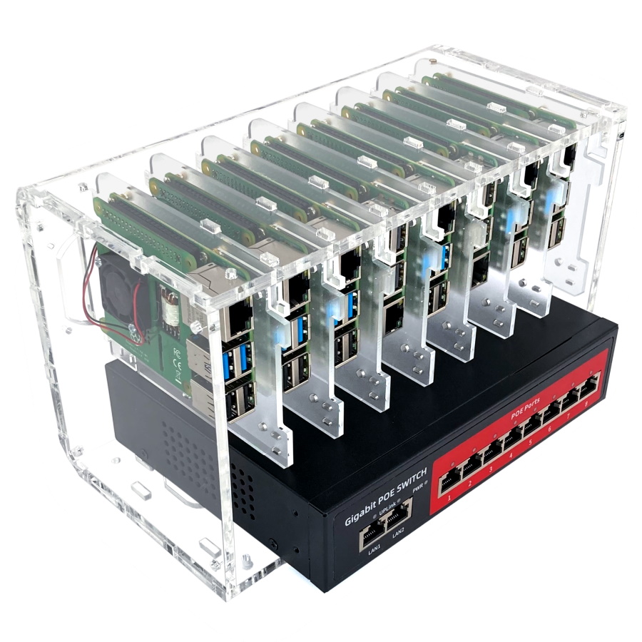 |
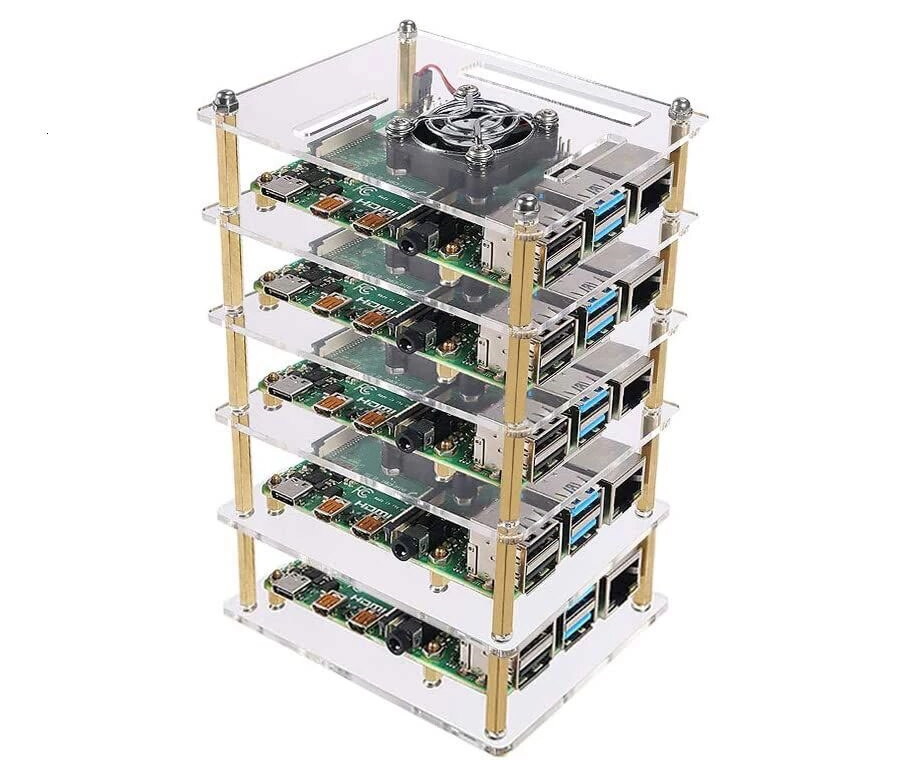 |
Fig 1: Examples of Raspberry Pi Cluster Enclosures
This is what made me think of aligning the Raspberry Pis in an offset pattern to allow for better airflow. I was thinking of using a Pringles box and aligning trays in a star shaped way.
The original idea and first model
The original idea was a 2D drawing and a model made from toilet paper rolls with Bristol board wings for the trays for the Raspberry Pis:
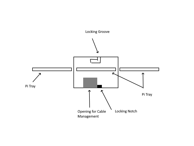 |
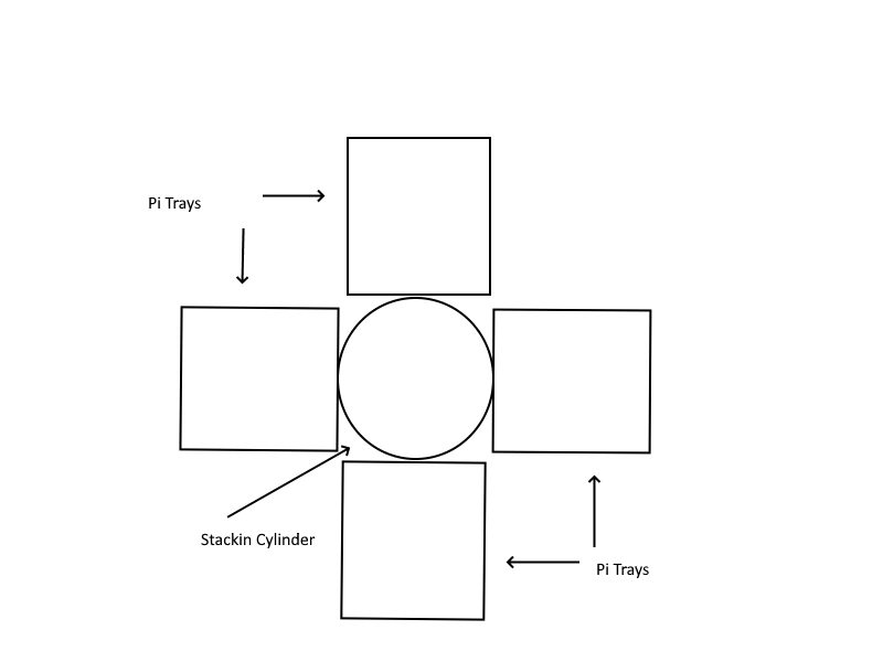 |
Fig 2: First Brainstorm Images of the Pi Cluster Tray
First Model:
Collage 1: Various Pictures of the First Pi Tray Model
The Pringles Prototype
For the next version of the Pi Tray prototype, I replaced the toilet paper rolls with a Pringles tube:
Collage 2: Various Pictures of the Pringles Pi Tray Prototype
First 3D Printed Prototype
As a next step, I thought maybe I could design and 3D print a modular tray that could allow for better air circulation. I found a guy on Fiverr who designed the first prototype of the Pi Tray.
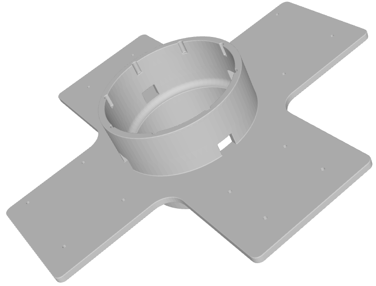
Fig 3: Pi Tray 3D Printed Prototype
Second 3D Printed Prototype
The problem with the original prototype was that it was too big to be printed on a standard 3D printer surface. It had to be printed in two pieces and then glued together.
Another improvement for the next iteration of the Pi Tray was that it was only designed with mounting holes for the LiM cluster board. So another guy, Sergiy L., on Upwork helped me design the next iteration of the Pi Tray. This time I had it designed it to fit on a standard 3D printer surface (220mmx220mmx250mm) as well as it should have mounting options for not only the LiM cluster board but also a Raspberry Pi 4B.
| Pi Tray v2 drawing | Pi Tray v2 3 levels drawing |
|---|---|
 |
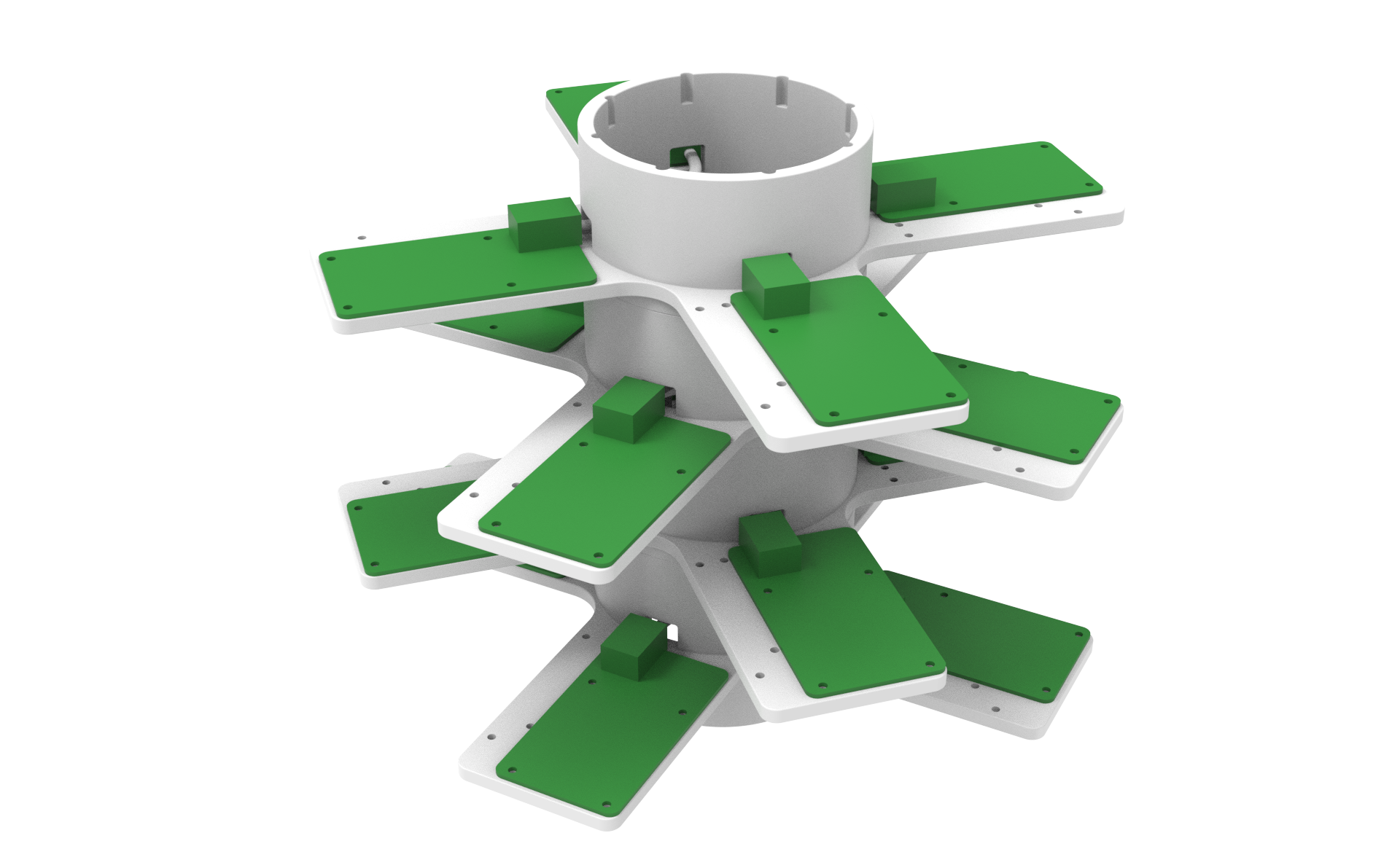 |
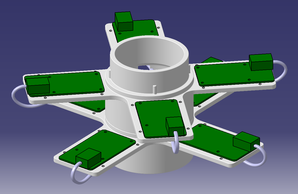
Fig 4: 3D Drawings of the Modular Pi Tray
Here are some pictures of the Pi Tray v2 printed, with a LiM cluster board and a Raspberry Pi 4B mounted:
Collage 3: Various Pictures of the 3D Printed Modular Pi Tray
So, after I had two Pi Tray modules printed and started to put a cluster together, I noticed I forgot to add notches in the bottom of the design to allow for the cables to come out of and allow the tray to be positioned evenly on a surface.
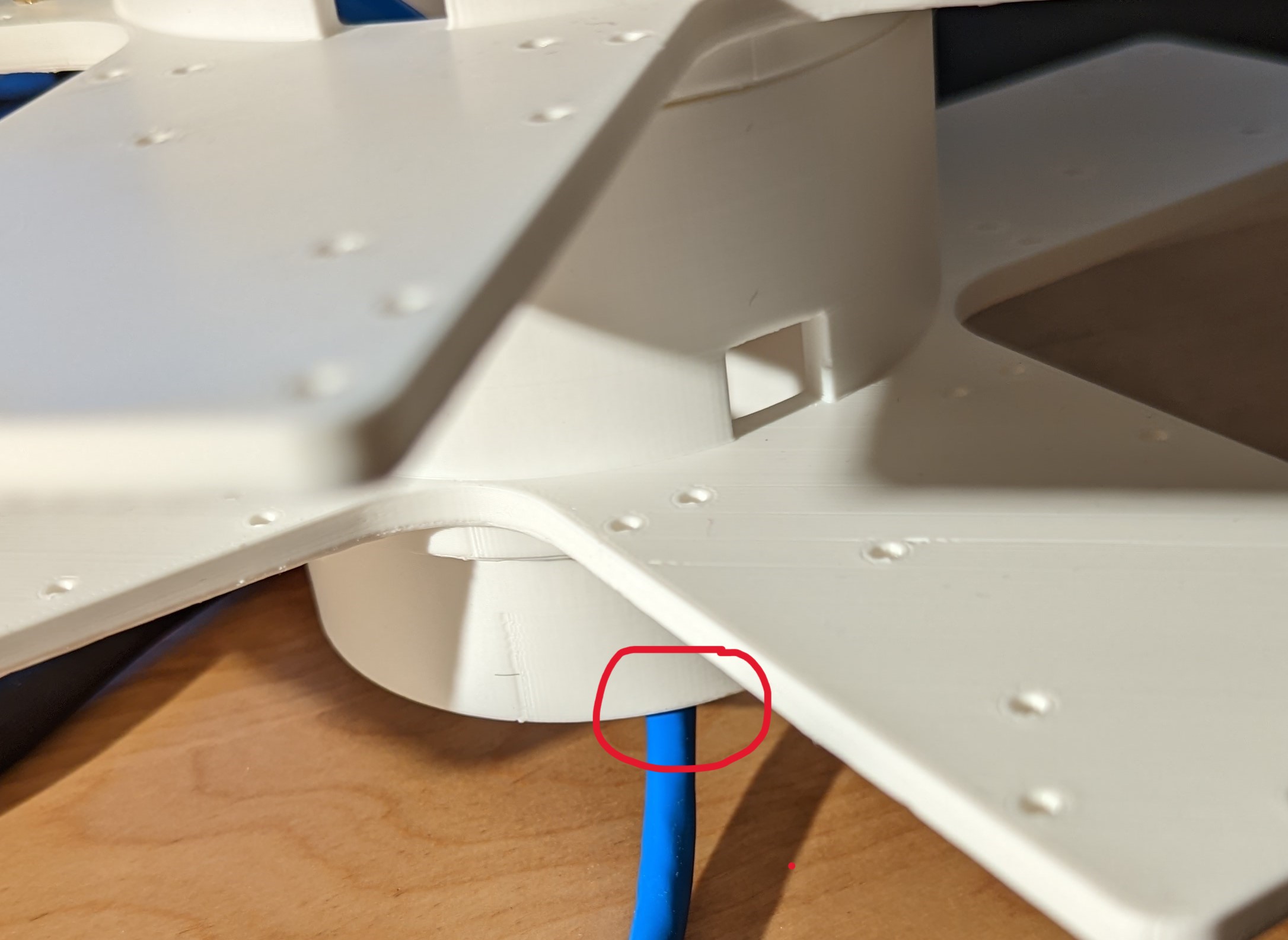
Fig 5: Pi Tray no notch
I did take a Dremel to one of the modules and added four notches to allow for the network cables to pass through. The final v3 of the Pi Tray will be updated to include these notches.
I will post pictures of the final v3 of the Pi Tray as well as the complete eight node cluster mounted on the modular trays when complete.
3 & 4 - Putting it all together - Building the cluster
After what felt like an eternity (2+ years) I had all the components together to finally build my LIM cluster.
Hardware Build
- The first step was to assemble the eight cluster nodes.
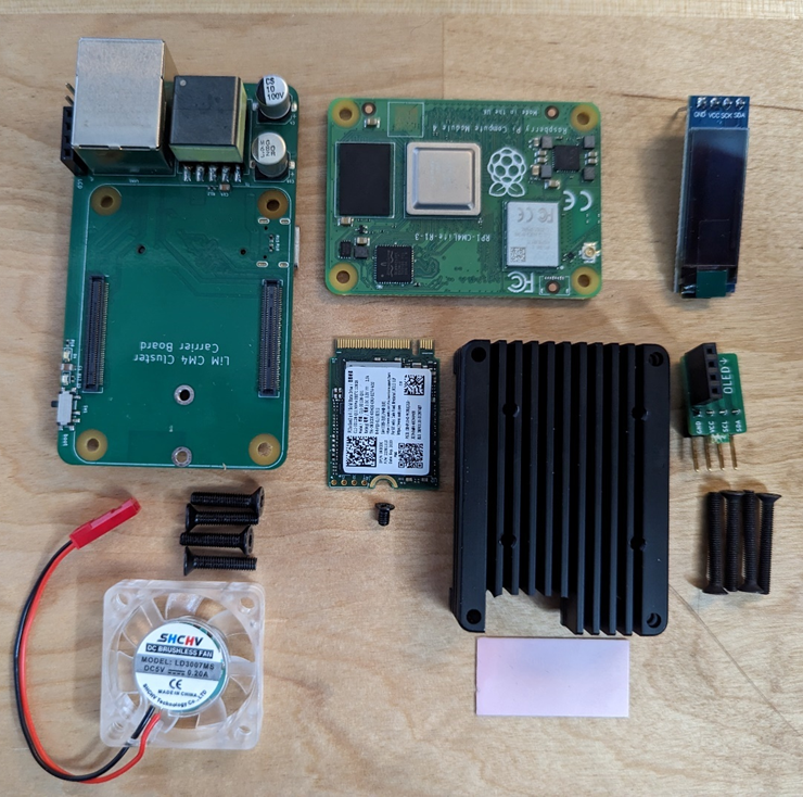
Fig 6: Depiction of all the parts making up a cluster node
Parts List:
- LiM CM4 Cluster carrier board
- Raspberry Pi Compute Module (CM) 4 Light 8GB RAM with WiFi - CM4108000
- 128x32 i2c OLED display
- 128GB 2232 M.2 M-key socket NVMe PCIe SSD drive
- CM4 Heat sink with thermal compound strip and screws
- Custom designed 90 degree i2c OLED angle bracket
- Brush less LED cooling fan CPU with screws
- Not pictured – M2.5 brass standoffs with screws
Assembly line, the parts to put all eight cluster nodes together:
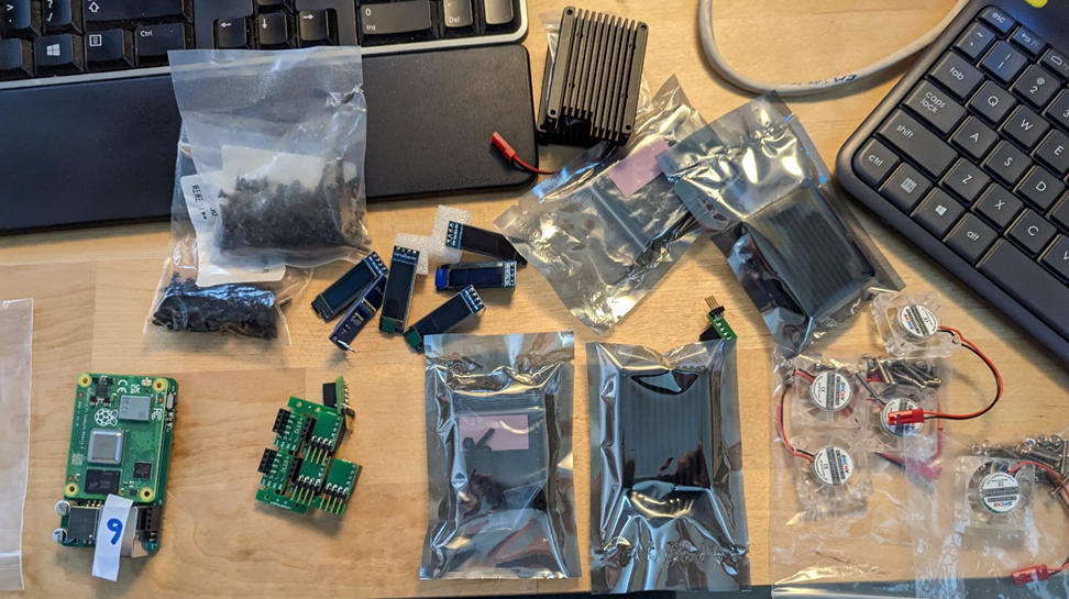
Fig 7: Parts pre cluster node assembly
And this is now how eight of the cluster nodes look like put together:
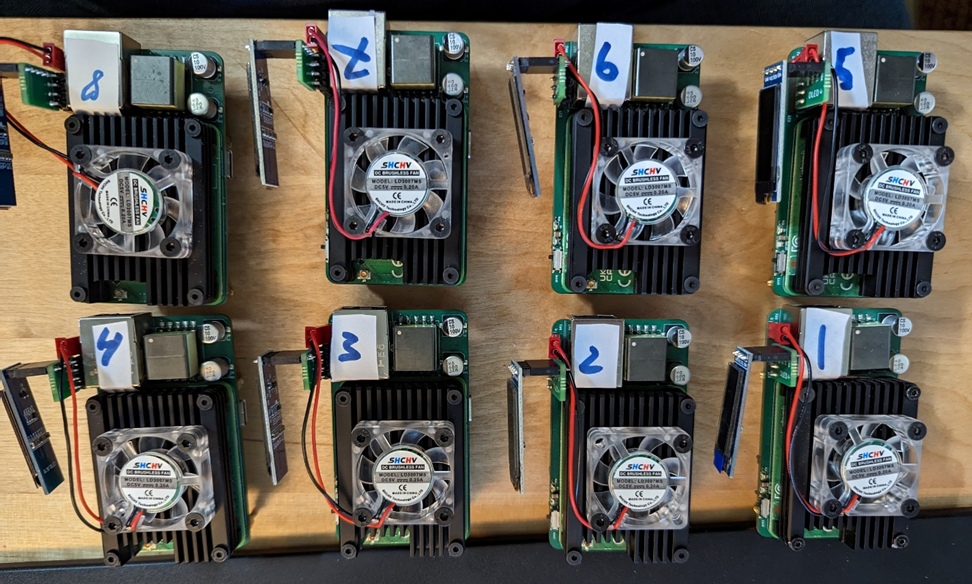
Fig 8: Eight cluster nodes fully assembled
Assembled cluster with eight cluster nodes in the Pi (Pringles) Tray standing on top of a 8 port PoE router:
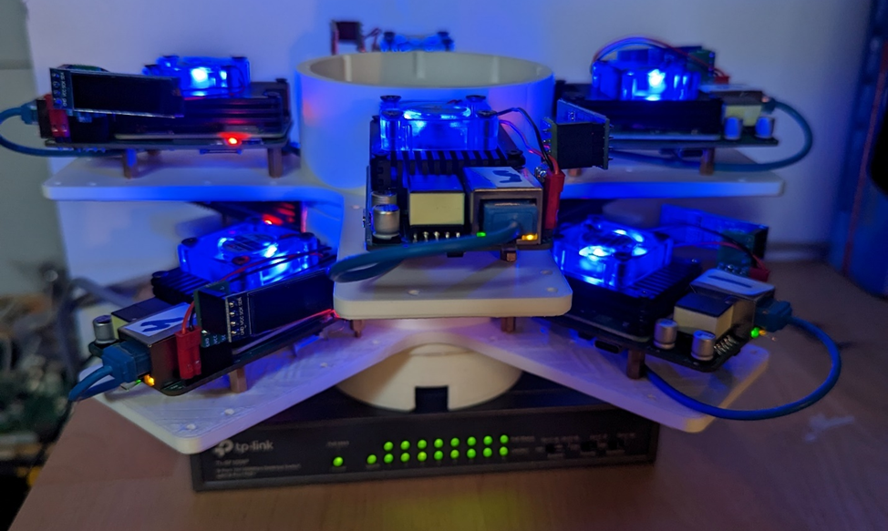
Fig 9: Complete cluster set up
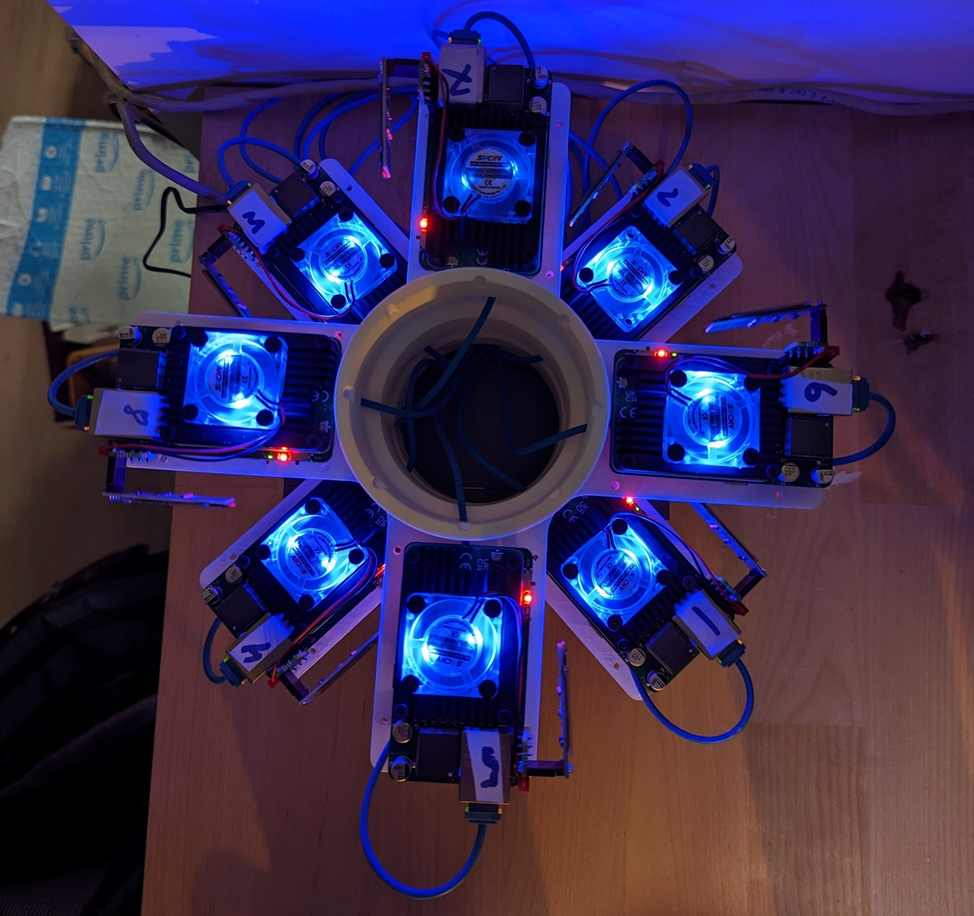
Fig 10: Cluster Top View
Software Build
Since I wanted to use Rancher to manage the cluster, I also prepared an Intel based UP 4000 Board and installed Ubuntu 22.04 and Rancher 2.5 on it (more on the Rancher install further down). I set this up as the ‘clustercontroller’ – 10.0.0.200. All the management of the cluster (Rancher, Ansible) is done from the clustercontroller node.
So, for the most part to install the cluster software I followed NetworkChuck’s video tutorial “i built a Raspberry Pi SUPER COMPUTER!! // ft. Kubernetes (k3s cluster w/ Rancher)”. I wanted to automate the cluster build as much as I could, so where possible I created Ansible scripts. But first, I needed to install Raspberry Pi OS on the cluster nodes.
- Imaging Since the cluster nodes are built with SSD drives, I used the Raspberry Pi Imager to write the OS to the eight SSD drives.
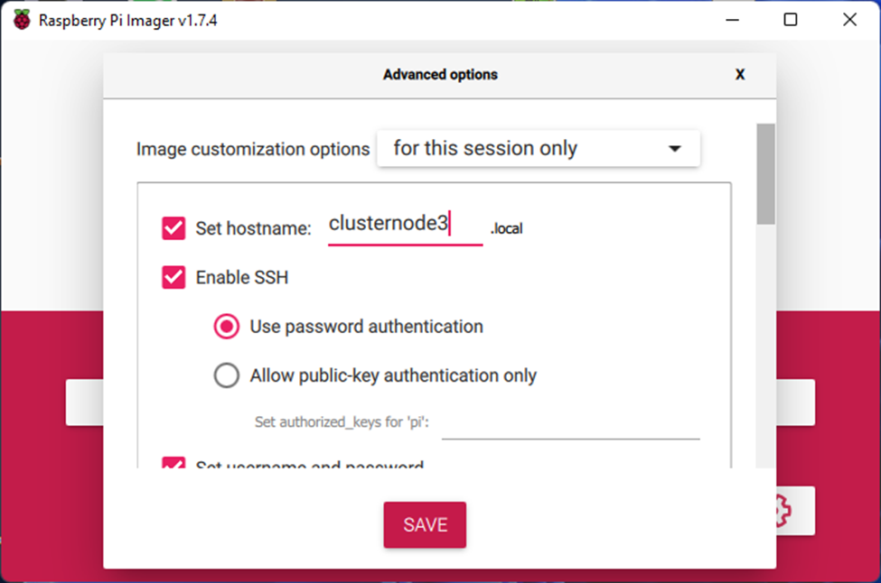
Fig 11: Raspberry Pi Imager
Initial set up/configuration:
- Enabled SSH
- I did not enable wireless as all nodes are using network cables connected to a PoE router which also power the nodes.
- I did not add “arm_64bit=1” to the config.txt file as I was already installing Raspberry Pi OS Bullseye 64-bit.
- All I changed in between imaging the next node was the hostname.
- From my test cluster set up I configured my ubiquity Dream machine to assign a static IP to each of the cluster nodes based on MAC address so I could easily identify the cluster nodes on my network. The IP address and hostname schema looks as follows:
- Cluster node 1: 10.0.0.201 – clusternode1
- Cluster node 2: 10.0.0.202 – clusternode2
- …
- Cluster node8: 10.0.0.208 – clusternode8
- Once I booted up all eight cluster nodes I copied ssh-keys across so I can communicate and administer the nodes from the clustercontroller. I created the following Ansible hosts file in /etc/ansible/:
[clustercontroller]
10.0.0.200

[clustermaster]
10.0.0.201

[clusterworkers]
10.0.0.202
10.0.0.203
10.0.0.204
10.0.0.205
10.0.0.206
10.0.0.207
10.0.0.208

[limcluster]
10.0.0.201
10.0.0.202
10.0.0.203
10.0.0.204
10.0.0.205
10.0.0.206
10.0.0.207
10.0.0.208

[testnode]
10.0.0.209
Then I tested it by pinging the cluster with Ansible:
Fig 12: Pinging all cluster nodes with Ansible
- Next, I updated the OS on all cluster nodes with the following Ansible script:
---
- hosts: "{{ variable_hosts  }}"
  remote_user: pi
  become: true
  become_user: root
  gather_facts: False

  tasks:
    - name: Update apt repo and cache on all Debian/Ubuntu boxes
      apt:
        update_cache: yes
        force_apt_get: yes
        cache_valid_time: 3600

    - name: Upgrade all packages on servers
      apt:
        upgrade: dist
        force_apt_get: yes

    - name: Check if a reboot is needed on all servers
      register: reboot_required_file
      stat:
        path: /var/run/reboot-required
        get_md5: no

    - name: Reboot the server if kernel updated
      reboot:
        msg: "Reboot initiated by Ansible for kernel updates"
        connect_timeout: 5
        reboot_timeout: 300
        pre_reboot_delay: 0
        post_reboot_delay: 30
        test_command: uptime
      when: reboot_required_file.stat.exists
Fig 13: Updating and rebooting Raspian OS on all cluster nodes with Ansible
- To add
“cgroup_memory=1 cgroup_enable=memory”I wrote the following Ansible script so I can easily do this across multiple cluster nodes and also easily add additional nodes if wanted/needed:
---
- hosts: "{{ variable_hosts  }}"
  remote_user: pi
  become: true
  become_user: root
  tasks:
    - name: Check whether /boot/cmdline.txt contains 'cgroup_memory' and append recommended cluster node vars if not found
      command: "grep  'cgroup_memory' /boot/cmdline.txt"
      register: checkmyconf
      check_mode: no
      ignore_errors: yes
      changed_when: no
      failed_when: false
    - meta: end_host
      when: checkmyconf.rc == 0

    - name: Add cgroup_memory to /boot/cmdline.txt
      ansible.builtin.lineinfile:
        path: "/boot/cmdline.txt"
        backrefs: true
        regexp: '^(.*rootwait.*)$'
        line: '\1 cgroup_memory=1 cgroup_enable=memory'
      register: updated
      when: checkmyconf.rc != 0

    - name: Reboot when /boot/cmdline.txt was updated with recommended cluster node vars
      reboot:
        connect_timeout: 5
        reboot_timeout: 300
        pre_reboot_delay: 0
        post_reboot_delay: 30
        test_command: uptime
      when: updated.failed == false
Fig 14: Adding additional parameters to the Raspian OS configuration with Ansible
- I DID NOT follow ‘Step 2 – K3s Prep’ of NetworkChuck’s tutorial and skipped the configuration of legacy IP tables. I continued NetworkChuck’s tutorial with the installation of the masternode of the k3s cluster. The k3s master node install is a ‘one liner’, an Ansible script is maybe a bit overkill but because I can, created the following Ansible script for the installation of the masternode:
---
- hosts: "{{ variable_hosts  }}"
  remote_user: pi
  become: true
  become_user: root
  tasks:
    - name: Check if k3s is already installed
      register: k3s_installed
      stat: path=/usr/local/bin/k3s get_md5=no

    - name: k3s is already installed and exit
      debug:
        msg: "k3s is already installed on {{ ansible_hostname }}"
      when: k3s_installed.stat.exists

    - meta: end_host
      when: k3s_installed.stat.exists

    - name: Install k3s on master node remote target
      shell: curl -sfL https://get.k3s.io | INSTALL_K3S_VERSION="v1.21.1+k3s1" K3S_KUBECONFIG_MODE="644" sh -s –
Fig 15: Installing k3s on the master node with Ansible
- Next, on to installing the cluster nodes with this Ansible script:
- hosts: "{{ variable_master  }}"
  gather_facts: false
  user: pi
  become: true
  become_user: root
  tasks:
     - name: "Read k3s cluster master token"
       shell: |
         cat /var/lib/rancher/k3s/server/node-token
       register: file_content
     - name: "Add k3s cluster master token to dummy host"
       add_host:
         name: "master_token_holder"
         hash: "{{ file_content.stdout }}"
         ip: "{{ inventory_hostname }}"

- hosts: "{{ variable_worker  }}"
  user: pi
  tasks:
    - name: Check if k3s is already installed
      register: k3s_installed
      stat: path=/usr/local/bin/k3s get_md5=no

    - name: k3s is already installed and exit
      debug:
        msg: "k3s is already installed on ""{{ ansible_hostname }}"
      when: k3s_installed.stat.exists

    - meta: end_host
      when: k3s_installed.stat.exists

    - name: Install k3s worker on remote target
      shell: curl -sfL https://get.k3s.io | INSTALL_K3S_VERSION="v1.21.1+k3s1" K3S_KUBECONFIG_MODE="644" K3S_TOKEN="{{ hostvars['master_token_holder']['hash'] }}" K3S_URL="https://"{{ hostvars['master_token_holder']['ip'] }}:6443" K3S_NODE_NAME="{{ ansible_hostname }}" sh -
Fig 16: Installing k3s on the worker nodes with Ansible
- After I had the cluster installed and running, I followed NetworkChuck’s instructions to install Rancher 2.5 on my clustercontoller
Fig 17: Rancher log in screen after install on the clustercontroller
- Once Rancher was installed, I connected the limcluster to it
Fig 18: Importing the k3s cluster into Rancher
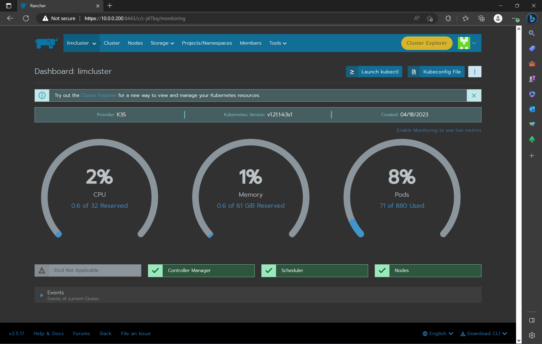
Fig 19: Cluster statistics displayed in Rancher Dashboard
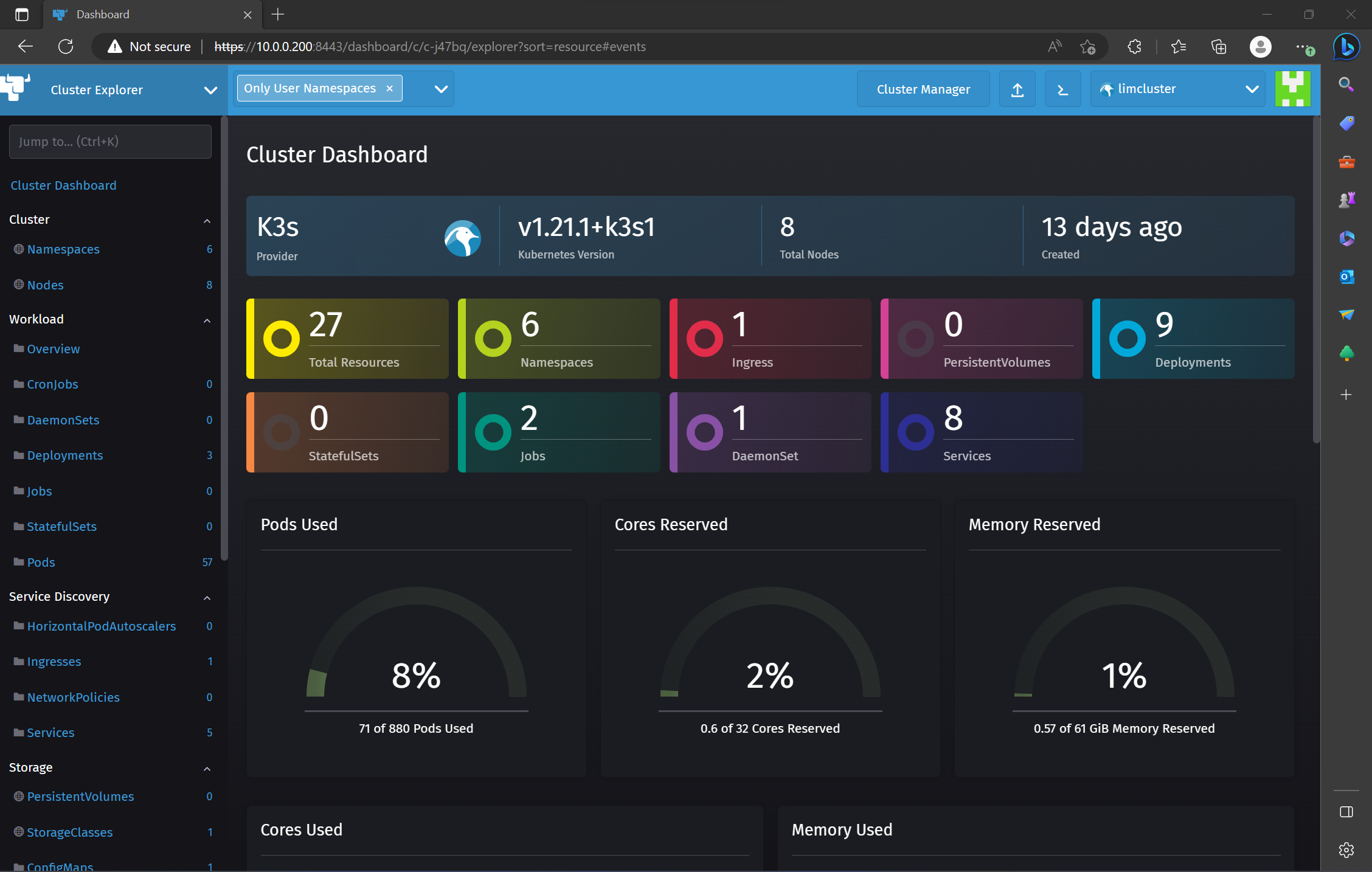
Fig 20: Cluster statistics displayed in Rancher 'Cluster Explorer'
I now had a functioning 8 node k3s cluster set up, managed by Rancher.
Testing the Cluster
- Now that the limcluster was set up, I followed NetworkChuck’s demos and first installed a couple of instances of nginx
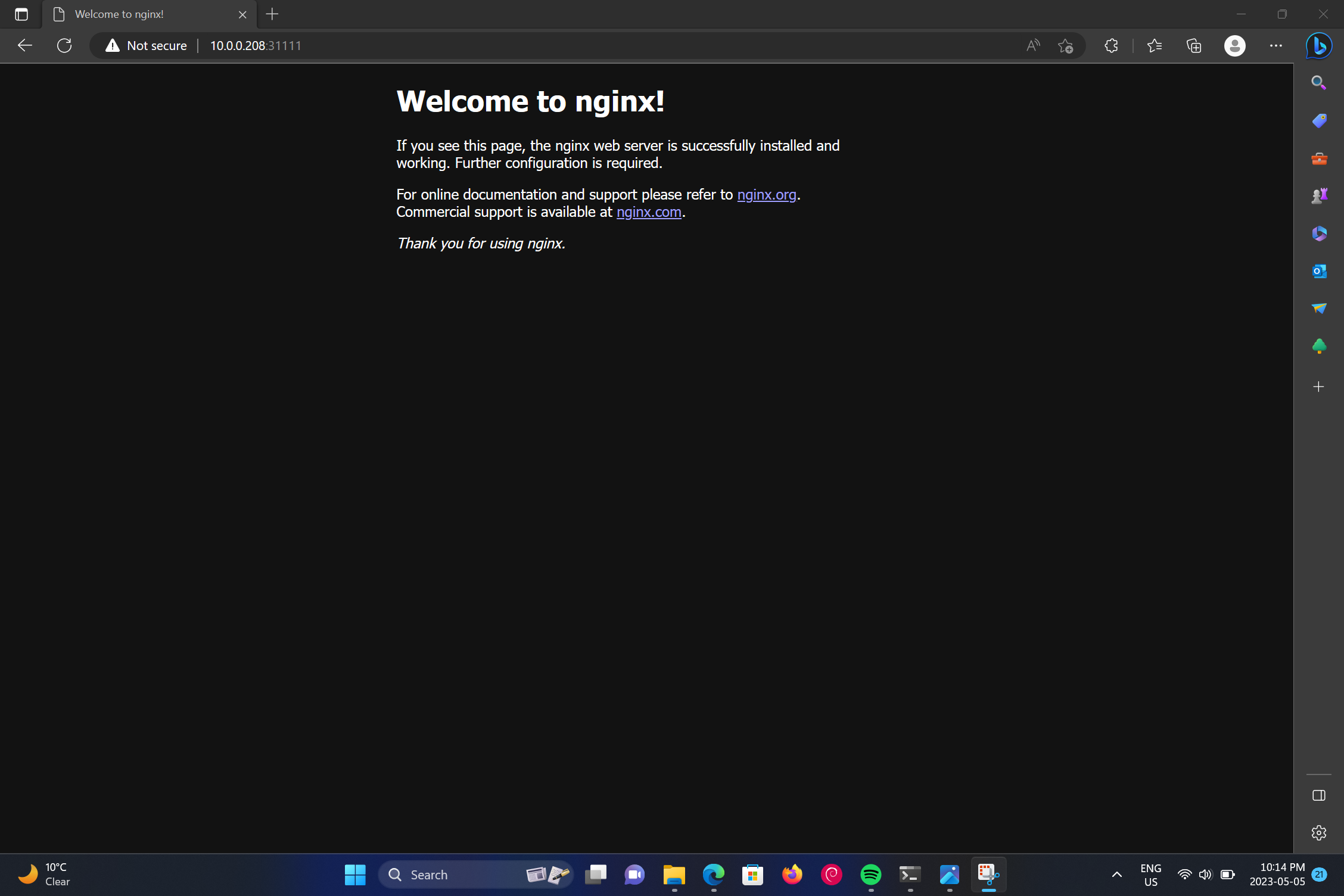
Fig 18: Nginx serving sample web page on the cluster
- After that, I tried the load balancing demo
Fig 19: Rancher 'Hello World' load balancing demo running on the cluster
- I also did get the Minecraft server install working via Rancher GUI, exactly as described by NetworkChuck in his video.
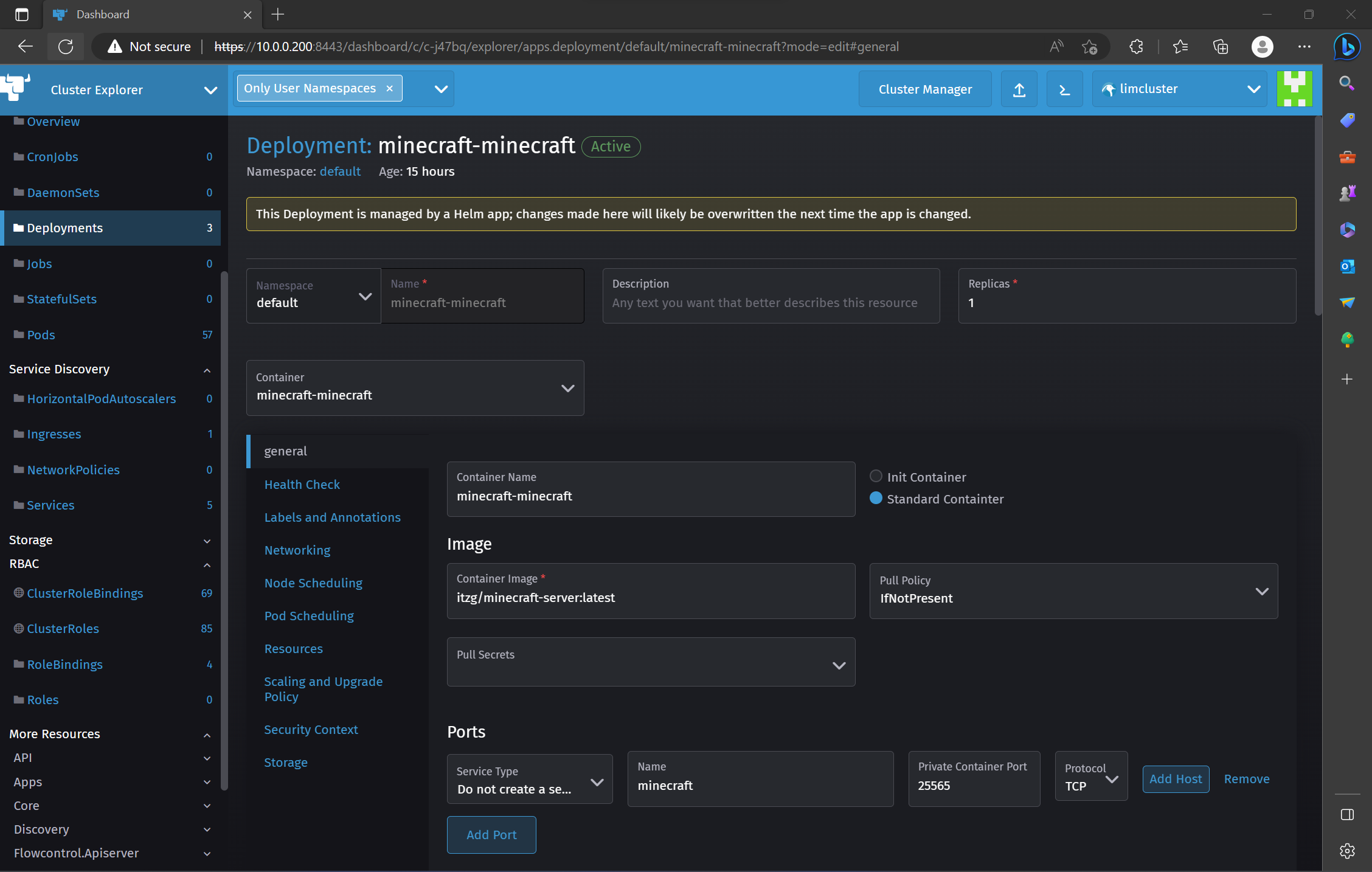
Fig 20: Minecraft deployment in the Rancher GUI
Fig 21: Minecraft Java edition connecting to the minecraft server running on the limcluster
Note: I did run into an issue that caused the minecraft deployment to ‘crashloop’ and constantly reboot. The issue is described here:
I fixed it by changing the following values in the helm chart for the minecraft deployment:
...
livenessProbe:
...
   initialDelaySeconds: 90
...
readinessProbe:
...
   initialDelaySeconds: 30
...
Additional (Optional) - Adding an OLED display
- The last step for me was to get the OLEDs working to display the stats of each node.
This was more of a fun add on that is not really necessary for the functionality of the cluster but I thought it would be nice to display basic system information on a small OLED display for easier identification of the indidual nodes.
See my seperate page on this side project for now: oleddisplaystats and the more Raspberry Pi/limcluster specific: displaypistats